I wanted to put together something simple, reliable and robust. I have looked into building my own motor drivers from plans on the internet, but that meant lots of design, ordering components, circuit layout, testing and loads of mess in the living room/Neil Lab.
Looking at commercial motor controllers for a separate robot project, I found this...
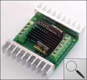
Here is a summary of the Specs...
Up to 18V in: 10A continuous, 15A peak per channel.
24V in: 8A continuous, 10A continuous with additional heatsinking/airflow, 15A peak per channel.
Synchronous regenerative drive
Ultra-sonic switching frequency
Thermal and overcurrent protection
Lithium protection mode
Input modes: Analog, R/C, simplified serial, packetized serial
Input voltage: 6-24V nominal, 30V absolute max.
Looking at the product manual I came across this example of an analog input setup...

The two potentiometers in the picture are connected between the V+(5V) and Ground connections on the board and the center wiper of the pot is connected to the S1 or S2 analog input on the board.. In this configuration, when the pot is centered the input should show 2.5v and the motor on that channel is stopped. Between 0V and 2.5V is reverse and from 2.5V to 5V is forward. When I saw the picture above, I knew it could easily be converted to a Voltage Divide Photo-Bridge with two photodiodes....


USB LED Laptop Light
£1.75 Buy it Now price with free UK postageWe shall see if I can easily replace the LEDs with the photodiodes when they arrive...stay tuned

http://www.livingonsolar.com/solar-tracking.html
ReplyDelete